Project ITS Architectures
The definition of a Project level ITS architecture, taken from 23 CFR 940 on Intelligent Transportation System Architecture and Standards is "a framework that identifies the institutional agreement and technical integration necessary to interface a major ITS project with other ITS projects and systems".
A project ITS architecture contains similar components to a regional ITS architecture, except the scope of it is a single ITS project, and the life cycle of the project architecture concludes with the completion of the project.
There are two related ways to develop a project ITS architecture:
1. As part of a regional ITS architecture development, by creating projects within the Regional Architecture Development for Intelligent Transportation (RAD-IT) software tool
2. As a more detailed architecture created in the Systems Engineering Tool for Intelligent Transportation (SET-IT), that may optionally be linked to the corresponding project in RAD-IT.
Purpose of a Project ITS Architecture
The purpose of developing a project ITS architecture is to illustrate and document, in the context of a regional ITS architecture, a representation of the project that can be used to support systems engineering outputs for the project, including the systems engineering analysis requirements defined in 23 CFR 940.11.
Components of a Project ITS Architecture
A project ITS architecture can be described by the following set of components:
- Stakeholders
- Operational Concept (user needs plus stakeholder roles and responsibilities)
- ITS Services (both existing and planned)
- Elements (or systems used to deploy ITS services)
- Interfaces supporting the services
- Agreements existing or planned to support the project
- System functional requirements
- ITS Standards applicable to the project
The components listed above apply to both approaches to developing a project ITS architecture listed above. The difference will be in the level of detail the project ITS architecture contains for some of the components such as requirements, interfaces, and ITS standards, and the corresponding value provided to architecture users. Each component above is linked to a separate page that explains the nature of the component when the project ITS architecture exists within a RAD-IT file, and then the additional level of detail for that component that can be created if the project ITS architecture is created using SET-IT.
Architecture Reference for Cooperative and Intelligent Transportation (ARC-IT) is used as a template to create project ITS architectures that are tailored for a specific ITS project. ARC-IT provides the fundamental building blocks: the physical objects (subsystems and terminators), interfaces (as defined by the information flows), service packages, user needs, etc., that are selectively included in the project ITS architecture and customized as necessary to fully reflect the details of the project.
Project Scope
Project Scope is a concise description of the project. It may be augmented by additional information about the project as described below.
Details Defined in RAD-IT
 The information about
project scope can be found on the Start page of RAD-IT when the project is
selected on the left side of the Start page (see figure below). In addition to
the project description, the start page includes a definition of the geographic
and scope of services for the project.
The information about
project scope can be found on the Start page of RAD-IT when the project is
selected on the left side of the Start page (see figure below). In addition to
the project description, the start page includes a definition of the geographic
and scope of services for the project.
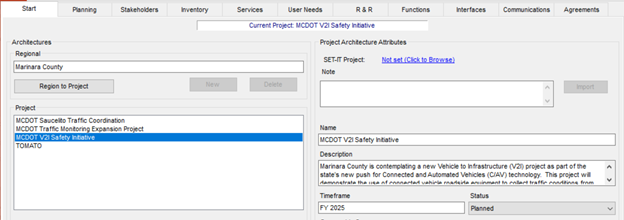
Project Architecture Start Tab in RAD-IT
Details Defined in SET-IT
 The key information about project
scope is contained on the Overview Project page. As shown on the page, the
project has a name and description along with the following information:
The key information about project
scope is contained on the Overview Project page. As shown on the page, the
project has a name and description along with the following information:
- Geographic Scope: this is a text box to put where will the project be deployed
- Services Scope: this is a text box to describe what are the key ITS services that will be deployed
- Procurement Strategy: this is a text box to add a description of the procurement strategy applied to the project
- Operations Resources: this is a text box to add a description of the operations resources that will be required once the project is deployed.
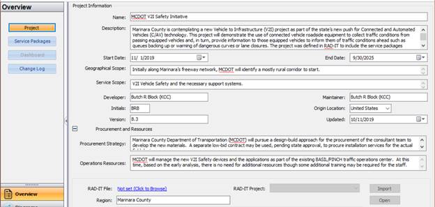
Project Information for Sample Project in SET-IT
Using the Component
The Project scope information contained in either RAD-IT or SET-IT can be used in documentation about the project, such as the Concept of Operations. The additional information that can be entered into the SET-IT Overview (Procurement Strategy and Operations Resources) can be used to address two requirements of 23 CFR 940.11 systems engineering analysis, which requires the following be identified:
- Procurement options;
- Procedures and resources necessary for operations and management of the system.
Stakeholders
Stakeholders are the agencies and organizations that own, operate, maintain or use the ITS systems that are a part of the project. These stakeholders could include both public and private organizations.
Details Defined in RAD-IT
The key information about stakeholders is
contained on the Stakeholders tab of RAD-IT. As shown on the tab, each
stakeholder has a name and description. The Stakeholders
tab on RAD-IT is shown below and is the tab where the initial updates of
stakeholder names or descriptions are performed.
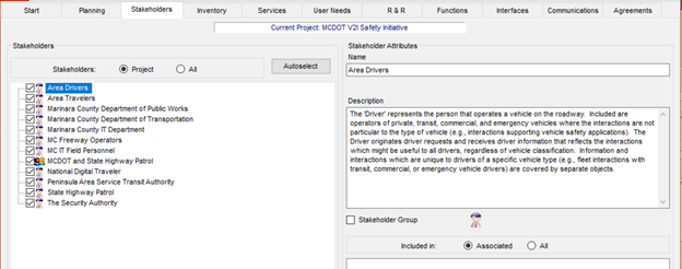
Project Architecture Stakeholders Tab in RAD-IT
Stakeholders are mapped to several other components of the architecture. The updates of each of these components will require that their mapping to stakeholders is also updated. Based on the way RAD-IT works, an update to stakeholder information on the Stakeholders Tab will automatically be updated in the mapping to stakeholders on the other tabs.
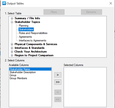
The key outputs used to discuss stakeholders are either a table, which can be created by going to the RAD-IT top menu Output/Tables and selecting the Stakeholder Table shown below, or going to the Stakeholders tab on an architecture website.
 Create a Stakeholder Group when you want to associate more than one
stakeholder with the same element. This could be a group of stakeholders, such
as several emergency services agencies, that may be in charge of an emergency
center in the Regional Architecture which is actually a group of emergency centers.
On the Stakeholders tab of RAD-IT, individual stakeholders are represented by
the single person icon while stakeholder groups are shown using the multiple
person icon.
Create a Stakeholder Group when you want to associate more than one
stakeholder with the same element. This could be a group of stakeholders, such
as several emergency services agencies, that may be in charge of an emergency
center in the Regional Architecture which is actually a group of emergency centers.
On the Stakeholders tab of RAD-IT, individual stakeholders are represented by
the single person icon while stakeholder groups are shown using the multiple
person icon.
Details Defined in SET-IT
The key information about Stakeholders is contained as a left tab on
the Definitions section of SET-IT. As shown on the tab, each stakeholder has a
name and description. With regards to stakeholders, the information is SET-IT
is comparable to that contained in RAD-IT. But the list of stakeholders in
SET-IT may be larger based on the different level of details in the elements
and interconnections that can be created in SET-IT.
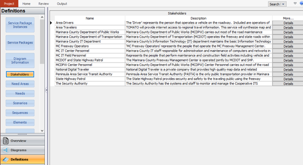
Stakeholders Grid for Sample Project in SET-IT
Using the Component
Stakeholder information, either from RAD-IT or SET-IT, would most likely be included as part of the Concept of Operations document. The list of stakeholders and their description are also one of the inputs that would be used to complete the Stakeholder Roles and Responsibilities aspect of the 23 CFR 940.11. Note that SET-IT includes the capability to produce a draft Concept of Operations, and will by default include all stakeholder definitions in that output.
User Needs
A user need is a capability that is identified to accomplish a specific goal or solve a problem that is to be supported by the system.
Details Defined in RAD-IT
The key information about User
Needs is contained on the User Needs Tab of RAD-IT. As shown on the tab, the
user needs are associated with each service package that is a part of the
project. The original set of user needs are taken from ARC-IT. In RAD-IT you
select which of those apply, you can also create new needs relevant to the
service.
Project Architecture User Needs Tab in RAD-IT
Details Defined in SET-IT
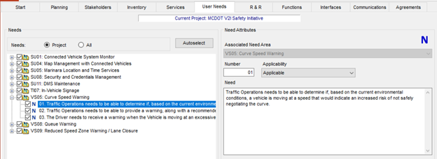
The key information about User Needs is found on the Needs tab on the
Definitions section of SET-IT. As shown on the tab, each user need is organized
by service package. As is the case with RAD-IT, you can add user needs beyond
those in ARC-IT. The one aspect of user needs in SET-IT
that goes beyond the information in RAD-IT is that each user need can be
assigned a priority. The default is low/medium/high as well as Not Applicable.
This feature allows you to prioritize the user needs in relation to your
project.
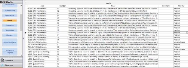
User Needs Definitions Grid in SET-IT
Using the Component
Getting stakeholder agreement on a project's needs is essential to the successful completion of every project. The user needs contained in either RAD-IT or SET-IT can be used as a starting point for the development of an individual project's needs. SET-IT also includes the capability to produce a draft Concept of Operations that will take all the needs defined in SET-IT and organize them by service in the chapter on Justification for and Nature of Changes. Note that SET-IT includes the capability to produce a draft Concept of Operations, and will by default include all user needs in that output.
Roles and Responsibilities
Typical roles for transportation stakeholders include that they own, develop, operate, or maintain portions of the transportation system. Responsibilities cover activities that the stakeholders engage in as they perform their roles. An example of a responsibility is that a municipal agency operates traffic signal systems on arterials while a state agency operates detectors and signage on the freeway.
Details Defined in RAD-IT
The
key information about Roles and Responsibilities is
contained on the R&R Tab of RAD-IT. For a project, these roles and
responsibilities are typically a subset of the roles and responsibilities
defined for the regional ITS architecture. The figure below shows an example of
R&Rs from the sample project in RAD-IT.
Project Architecture R&Rs Tab in RAD-IT
Note that in RAD-IT the R&Rs tend to be "responsibilities" as defined above. An example responsibility from the figure above is that the Marinara County Department of Transportation has the responsibility for "Monitor traffic flow on the freeways. Determine travel times.". The R&Rs in RAD-IT can be output as a table from the Output pulldown, as shown in the figure below. The table can be organized by stakeholder or by Role and Responsibility (RR) Area, e.g., Freeway Management.
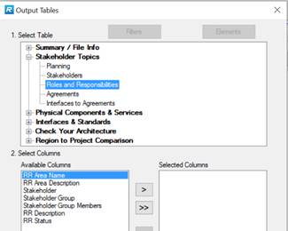
Roles & Responsibilities Output Tables Menu in RAD-IT
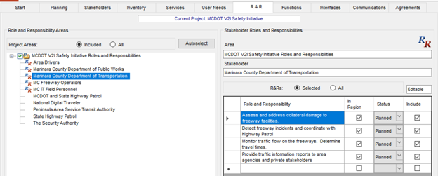
Details Defined in SET-IT
The key information about Roles and Responsibilities is found in the
Enterprise View, on the Stakeholder Roles tab on the Definitions section of
SET-IT. As shown on the tab, each stakeholder role is organized first by
stakeholder, then by role, then by element. The information in SET-IT, since it is part of the Enterprise
View, focuses on the Roles (e.g. owns, operates, maintains) of the stakeholder
with regard to the specific elements. So, in the figure shown below, the
Marinara County Department of Public Works (MCDPW) installs, owns, and manages
the MCDPW GARLIC Information System.
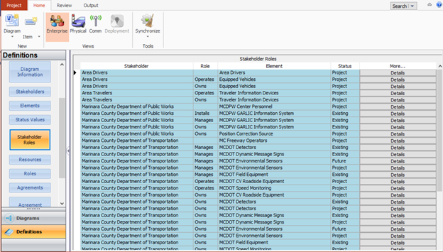
Stakeholder Roles Definitions Grid in SET-IT
SET-IT allows you to create an output of these roles by selecting the Output Tables tab, the Elements Table from the Enterprise View, and then sorting the resulting table as shown in the figure. The information can also be obtained
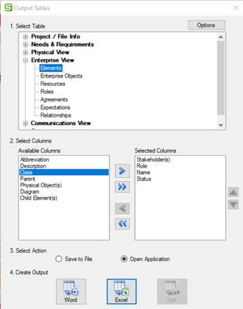
Output Menu for Element Stakeholder Roles
Using the Component
Services
ITS services are transportation services upgraded or improved by the project. These services are deployed in order to meet operational goals and objectives of the region. In a project ITS architecture these ITS Services can be described by customized ARC-IT service packages, which identify the elements and information flows needed to provide each ITS service.
Details Defined in RAD-IT
The key information about ITS services is on the Services Tab in
RAD-IT. This tab shows which service packages are a part of the project.
Because of the high level nature of regional ITS architectures, many projects
are covered by one or two service packages in RAD-IT. The example below, from
the Sample architecture in RAD-IT, shows a more complex project that takes nine
service packages to full describe. For each service pacakge the elements that
are a part of the project's implementation of the service are identified.
Project Architecture Services Tab in RAD-IT
RAD-IT can output diagrams and tables related to the Service Packages for the project. The table below shows a portion of the output table for the Sample Project (SP) shown above.
Example Project Service Package Output Table
|
SP # |
Service Package Name |
SP Instance |
Included Elements |
|
SU01 |
Connected Vehicle System Monitor |
Yes |
MC Field Maintenance Equipment |
|
MC Freeway Management Center (BASIL/PINCH) |
|||
|
MC IT Field Personnel |
|||
|
MCDOT CV Roadside Equipment |
|||
|
MCDPW GARLIC Information System |
|||
|
SU04 |
Map Management for V2I Safety Initiative |
Yes |
Digital Map System |
|
Equipped Vehicles |
|||
|
MC Freeway Management Center (BASIL/PINCH) |
|||
|
MCDOT CV Roadside Equipment |
|||
|
MCDPW GARLIC Information System |
|||
|
Traveler Information Devices |
|||
|
SU05 |
Location and Time Services for V2I Safety |
Yes |
Center Location and Time Source (LTS) |
|
Equipped Vehicles |
|||
|
Field Location and Time Source (LTS) |
|||
|
MC Freeway Management Center (BASIL/PINCH) |
|||
|
MCDOT CV Roadside Equipment |
|||
|
MCDPW GARLIC Information System |
|||
|
Position Correction Source |
|||
|
Traveler Information Devices |
Details Defined in SET-IT
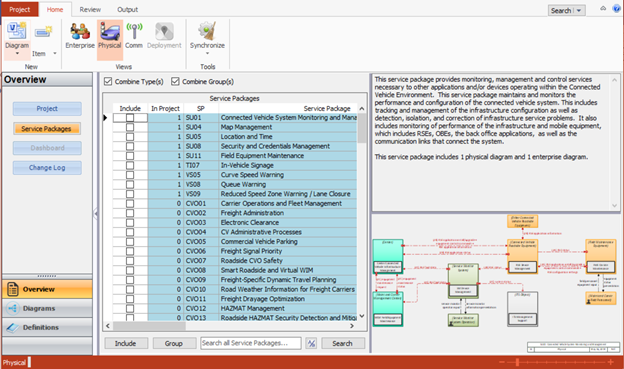
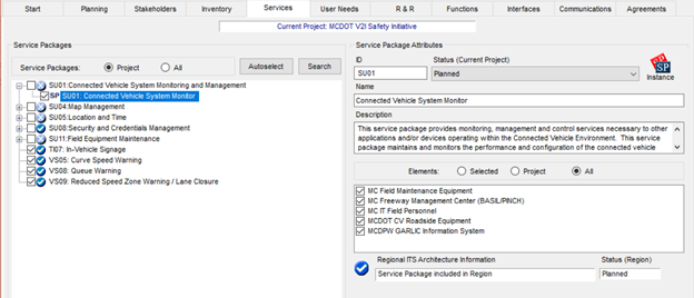
Service Packages Menu Screen in SET-IT
While the diagram on the Overview page shows the ARC-IT service package diagram, the project ITS architecture is defined by customizing these ARC-IT diagrams for the specific elements and interfaces that apply to the project. Selecting the Diagrams tab provides a window to each of the customized service package diagrams that define the architecture. The figure below shows the example project implementation of the service package In-Vehicle Signage.
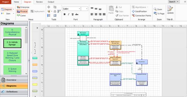
Service Package Diagram from SET-IT
Below is a larger version of the service package diagram. Note that for the project not all the elements and interfaces will be implemented. The diagram shows an interface between Pasta Equipment Bus Fleet and Equipped Vehicles, but does not include interfaces for Emergency Vehicles or Maintenance Vehicles, which are in the ARC-IT version of the service package. Also note that in the project ITS architecture the project elements are described with their connections. So for example, there an interface between MC Freeway Management Center and MCDOT Dynamic Message Signs, which are the elements that are being deployed for the project.
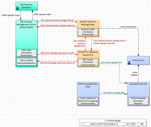
Service Package Diagram from SET-IT (Enlarged)
While SET-IT allows a project ITS architecture to be imported from RAD-IT, this usually serves as a starting point for creation of a more detailed project ITS architecture in SET-IT. The example project figure above includes additional details, such as the interfaces to Area Drivers and MC Freeway Operators, which would not be included in a regional ITS architecture.
SET-IT also provides the tools to specify details like the flow characterstics on each interface which will be discussed below. In SET-IT the user can also use the Sequence tool to document and show the sequence of steps that users might go through in a set of user scenaios. These scenarios can then be documented in the generated Concept of Operations.
Using the Component
A description, including diagrams or tables, of the project's services can be used in several aspects of projece development. Services are a key aspect of the CFR 940.11 systems engineering analysis (SEA) requirement relating to "Identification of portions of the regional ITS architecture being implemented", so you can use the information described in the RAD-IT or SET-IT sections above to partially address this SEA requirement. Some aspects of the services will likely be included in any Concept of Operations developed for the project, usually in the section relating to Justification for and Nature of Changes. A description, at a high level, of the new or revised services for the project is one of the best ways to describe the changes planned for the project. If a SET-IT file is created then the service package diagrams can provide a more detailed view of the changes. Note that SET-IT includes the capability to produce a draft Concept of Operations, and will by default include all project services in that output. In addition, the description of services should be included in the high level design document for the project. The high level design document should include a description of the project ITS architecture, using whatever information is available (from RAD-IT or SET-IT) and a description of the services, along with diagrams if available would definitely be a part of that description.
Elements
ITS Elements are the systems, or pieces of systems, that provide ITS services or share information as part of the ITS services. Each stakeholder agency, company, or group owns, operates, or maintains ITS systems in the region. Each project ITS architecture has a list of elements (called an inventory) which may also include non-ITS elements that provide information to or get information from the ITS elements.
Details Defined in RAD-IT
The key information about
the ITS elements can be found on the RAD-IT Inventory tab, where the names,
descriptions, associated stakeholder, status and mapping to ARC-IT components are
contained. The Inventory Tab on RAD-IT is shown below for a project in the
sample database.
Project Architecture Inventory Tab in RAD-IT
The most common output from RAD-IT for the elements is a table from the Output Tables, see the figure below. When creating an output table, a common approach is to create one sorted by Stakeholder, as shown in the figure below.
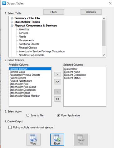
Output Menu for Element Inventory
Details Defined in SET-IT
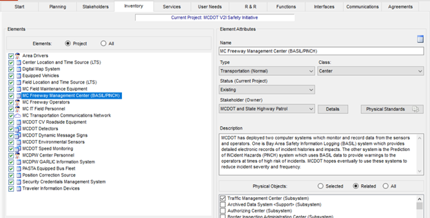
Information about which Elements are a part of the project can be found
on the Elements table or grid in the Definitions menu area. This page shows a
list of all the elements in the project. The page shows basic information about
the elements, with additional information on the Details tab.
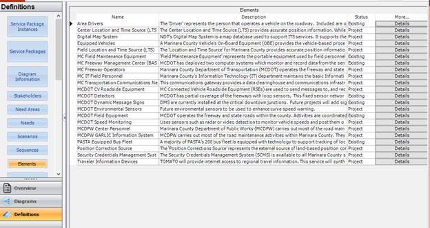
Elements Definitions Grid in SET-IT
Elements are also a key component of the Service Package diagrams that are part of the architecture. For example, the figure below shows the Queue Warning Service Package, with the elements of MCDOT highlighted in the diagram.
![]()
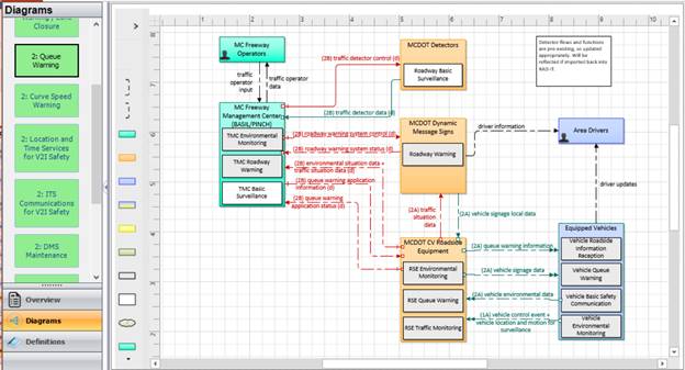
Service Package Diagram in SET-IT
The elements of the project
in SET-IT can be imported from the project in RAD-IT, and then augmented to
create a more detailed architecture for the project. The example above includes
the elements MC Freeway Operators and Area Drivers that would usually not be
included in a regional ITS architecture.
Using the Component
Interfaces
Interfaces are the electronic connections between ITS elements, which support the exchange of information between ITS elements. Interfaces can be defined by at two levels as:
- Interconnects: Communications paths that carry information between elements. Some of the key types of communications links relevant to regional ITS architectures are Center to Center (C2C), Center to Field (C2F), Field to Field (F2F), Wide Area Wireless (WAW), and Short-Range Wireless (includes Dedicated Short Range Communications or DSRC).
- Information Flows: Information that is exchanged between elements. Information flows are a high-level description of the electronic information transmitted from one element to another. These information flows and their communication requirements define the interfaces which form the basis for ITS standards.
Details Defined in RAD-IT
The key information about
the interfaces can be found on the RAD-IT Interface tab, where the tool allows
the user to define the interfaces between the transportation system elements in
the project.
There are various views and customization options for this tab. The view below shows the information exchange tab, with some of the information flows between the MC Freeway Management Center and MCDOT field elements. For the information flows between elements, each information flow is described by a source element (where the information originates), a destination element (where the information is sent) and a descriptive name for the information itself. The high-level status of the information flow (e.g., existing, planned, future, etc.), and whether the project information flow is included in the regional ITS architecture. The page also indicates if there is a communications element defined in the project that supports the information flow on the interface.
Project Architecture Inventory Tab in RAD-IT
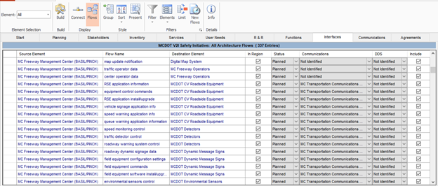
Details Defined in SET-IT
Information about Interfaces that are a part
of the project can be found on the Definitions- Information Flow Triples selection. The
definitions of the Information flows can be found at Definitions-
Information Flows.
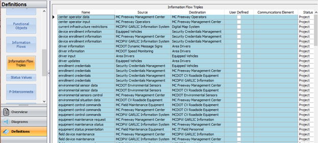
Information Flow Triples Definitions Grid in SET-IT
The Details tab on this latter page also provides considerable additional information about the characteristics of the information flow (e.g. time content, spatial content and cardinality) along with security considerations for the information flow defined by the Federal Information Processing Standards (FIPS) attributes of Confidentiality, Integrity and Availability.
The interfaces also play a key role in the service package diagrams. All the Information Flow Triples in the definition table show up in one or more of the Service Package Diagrams.
While the interfaces (and elements) imported from RAD-IT are a good
starting point for the definition of interfaces in SET-IT, take advantage of
the flexibility inherent in SET-IT to define new interfaces, or to add details
to the interfaces that are imported. The projects in RAD-IT are described at a
high level commensurate with the level of detail in a regional ITS architecture.
SET-IT can be used to add more details to the project ITS architecture that
provide a more complete description of the interfaces (and elements) that
makeup the project.
Using the Component
A description of the project's interfaces, either in tables or diagrams, can be used to support several aspects of project development. Interfaces are a key aspect of the CFR 940.11 systems engineering analysis (SEA) requirement relating to "Identification of portions of the regional ITS architecture being implemented", so you can use the information described in RAD-IT or SET-IT to partially address this SEA requirement. Interfaces will likely be included in any Concept of Operations developed for the project, usually in the section relating to Concept for Proposed System, which will discuss the new or revised interfaces to be implemented by the project. SET-IT supports the creation of a ConOps. In addition, the description of interfaces (and information flows) should be included in the high level design document for the project. The high level design should describe the project ITS architecture, using whatever information is available from RAD-IT or SET-IT, including the project's interfaces.
Agreements
To deploy the services defined for the project, agreements between stakeholders may be required especially when inter-jurisdictional interfaces are involved. The agreements may define the integration planned, the plans for maintaining and operating the elements and the funding responsibilities of the stakeholders.
Details Defined in RAD-IT
The Agreements Tab on RAD-IT is shown below and is the tab to use to
collect the list of existing agreements and the agreements potentially needed to
implement the project. Each list entry identifies the agreement title, the stakeholders
involved, the type of agreement that is anticipated, high level status
(existing or planned), and a concise statement of the purpose of the agreement.
The figure below shows a project in the Sample database with a planned
information exchange agreement between MCDOT and State Highway Patrol.
Project Architecture Agreements Tab in RAD-IT
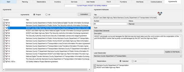
Details Defined in SET-IT
Information about Agreements that are a part of the project can be
found on the Enterprise View, Definitions- Agreements page. The figure below,
for the SET-IT sample project, shows the similar information for an information
sharing agreement between MCDOT and State Police shown in the RAD-IT figure
above. In addition to a tabular description of the agreements, SET-IT has the
capability to create a high level enterprise view diagram showing in graphical
form the agreements, roles, and expectations that connect stakeholders
together.
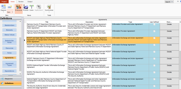
Agreements Definitions Grid in SET-IT
Using the Component
A description of the project's agreements can be used to support development of the Concept of Operations (ConOps) for the project. Agreements will likely be included in the section relating to Concept for Proposed System, which will discuss the agreements needed for the project. If the ConOps is developed based on a SET-IT file, then an Enterprise View, which includes agreements, may be a part of the outputs used in the ConOps. Note that SET-IT includes the capability to produce a draft Concept of Operations, and will by default include all the agreements in that output.
System Functional Requirements
Functional requirements are a high-level description of the required functionality for each ITS element to provide the ITS services that have been identified for the project. The functional requirements describe WHAT a system must do to provide the ITS services. As defined in the regional ITS architecture, these requirements are very high level. For a project ITS architecture, these are broken down into more detailed requirements to document fully the functionality of the system.
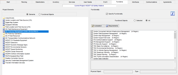
Details Defined in RAD-IT
The key information about system functional requirements is found on
the Functions tab of RAD-IT. As shown for the sample project below, for each
element there is a list of functional objects. This list is based on the
physical objects mapped to the element.
Project Architecture Functions Tab in RAD-IT
Selecting the Requirements button will open a new window that shows all the requirements defined for the selected Functional Objects. The figure below shows a subset of the Requirements for the element selected above. Note that some requirements are included and some are not, indicating that these requirements have been customized. Additional customization is allowed by tailoring requirements or creating new requirements.
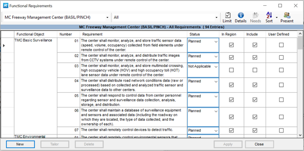
Functional Requirements Details Screen from RAD-IT
The functional requirements
in the project architectures in RAD-IT can be imported into SET-IT and used as
a starting point to create a more detailed view of requirements as discussed in
the Details Defined in SET-IT section below.
Details Defined in SET-IT
Information about requirements that are a part of the project can be
found on the Definitions- Requirements selection. This page shows a list of all
the requirements defined for the project. The page shows basic information
about the requirements similar to that shown in RAD-IT, including:
- the element the requirement applies to,
- functional object,
- requirement number,
- requirement text and
- whether the requirement is user defined, or taken from ARC-IT.
In addition, this tab includes additional information about the requirement including:
- Need addressed by the requirement- these originate as needs defined by Service Package, but can be revised to be user needs for the project.
- Source of the Requirement- most requirements originate with ARC-IT, but if you make the choice to create more detailed requirement, then these can be identified as developed for the project.
- Verification method for requirement- you have the ability to assign one of the four methods (analysis, inspection, demonstrate, or test)
The figure below shows the requirements defined for the sample project.
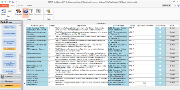
Requirements Definitions Grid in SET-IT
SET-IT has a second tab for requirements that show the requirements defined for each element.
Using the Component
A listing of the project's requirements can be used in several aspects of project development. Requirements are a key aspect of the CFR 940.11 systems engineering analysis (SEA) requirement relating to "Requirements definitions", so you can use the information described in the RAD-IT or SET-IT sections above to partially address this SEA requirement. Requirements are a key output of the systems engineering process, so any level of detail relating to requirements contained in RAD-IT or SET-IT can be used to begin the requirements development process. If more detailed requirements are defined or developed in SET-IT, then these can be used in the project development.
ITS Standards
ITS standards are documented technical specifications sponsored by a Standards Development Organization (SDO) to be used consistently as rules, guidelines, or definitions of characteristics. ITS Standards are primarily defined for interfaces between ITS elements, but they can also be defined for the physical characteristics of ITS elements as in the cabinet and traffic controller standards developed by NEMA and other organizations and SAE standards developed for motor vehicles.
Details Defined in RAD-IT
ARC-IT maintains a mapping of information flows to the collection of communications protocols and data definitions that can be used to implement the information flow. The Communications View pages of the ARC-IT website include the latest mapping between ARC-IT and the ITS communications solutions. RAD-IT accesses this mapping information and makes it available for review and customization. The "Communications" tab in RAD-IT provides the opportunity to decide which of the ITS Communications Solutions best applies to the region. Use the Communications Tab in RAD-IT to see the full list of communications solutions that are part of the architecture and use it when there are unique situations for your region, e.g. your state/region requires a certain standard interface for certain elements and you need to show that at the regional level.
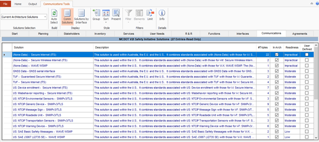
Project Architecture Standards Tab in RAD-IT
Details Defined in SET-IT
Information about standards that are a part of the project can be found on the Comm View, which contains a variety of information under the Definitions Tab. This tab contains the following information about the communications solutions that can apply to the project.
- Flow Triples to Solutions- a mapping of possible communications solutions to individual triples.
- Solutions- sets of standards that cover data definition, communications protocols, and security
- Standards- the individual standards that make up the communications solutions
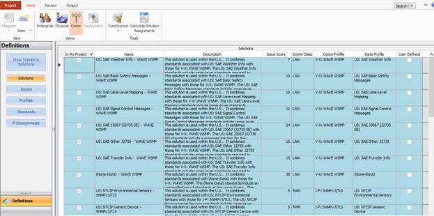
Project Communications View Tab in SET-IT
Using the Component
A description of the standards that are part of the communications solutions are a key aspect of project development. Definition of the standards is a requirement of 23 CFR 940.11 systems engineering analysis (SEA), which requires "Identification of applicable ITS standards and testing procedures", so you can use the information described in the RAD-IT or SET-IT sections above to partially address this SEA requirement (both tools identify standards, but not testing procedures).
One of the key parts of the systems engineering design step of the process is to identify interfaces and the standards that would be used to implement the interfaces. One of the key improvements of Version 9 in both RAD-IT and SET-IT is that rather than defining a flat set of standards, both tools define communication solutions that consider the set of standards needed to implement a triple in the project.