Physical
The physical view describes the transportation systems and the information exchanges that support ITS. In this view, the Architecture is depicted as a set of integrated Physical Objects (Subsystems and Terminators) that interact and exchange information to support the Architecture service packages. Physical Objects are defined to represent the major physical components of the ITS Architecture. Physical Objects include subsystems, and terminators that together provide a set of capabilities that are more than would be implemented at any one place or time. Subsystems are Physical Objects that are part of the overall Intelligent Transportation System and provide the functionality that is 'inside-the-boundary' of ITS. Terminators are Physical Objects that lie at the boundary of ITS and supply information needed by ITS' functions or receive information from ITS. Functional Objects break up the subsystems into deployment-sized pieces and define more specifically the functionality and interfaces that are required to support a particular Service Package. Information Flows depict the exchange of information that occurs between Physical Objects (Subsystems and Terminators). The information exchanges in the Physical View are identified by Triples that include the source and destination Physical Objects and the Information Flow that is exchanged.
The Physical view is related to the other Architecture views. Each Functional Object is linked to the Functional View, which describes more precisely the functions that are performed and the details of the data that is exchanged by the object. Physical Objects and Functional Objects are also depicted as Resources in the Enterprise view, which describes the organizations that are involved and the roles they play in installing, operating, maintaining, and certifying all of the components of the Architecture.
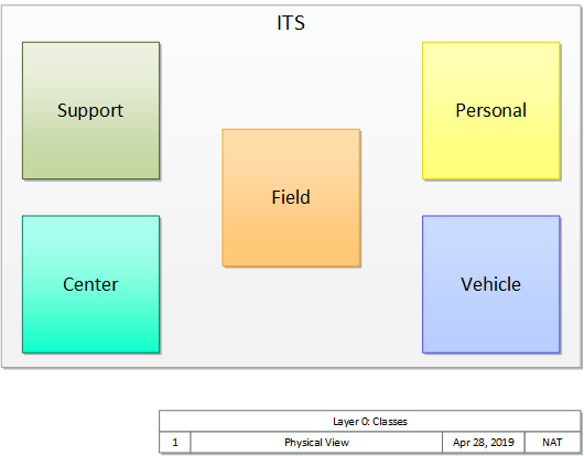
At the heart of the physical view, the physical objects are organized into six different Classes that define ITS at the highest level of abstraction. A general "ITS" Class covers all of ITS while five more specific classes (Center, Support, Field, Vehicle, and Personal) are used to group physical objects based on where they reside and fundamentally how they behave and interact with other physical objects. Each of the classes is shown in the figure below.
Considering the architecture from this most abstract (highest) level, the general interactions between physical objects can be shown at the class level as shown in the figure below. Note that all of the interactions (Center to Center, Center to Field, etc.) are part of ITS, so they are all included in the ITS Class. Only specific interactions apply to the more specific classes. For example, the Center to Center interaction only applies to Center- and Support-Class physical objects. Center to Center communications does not apply to Field-, Vehicle-, or Personal-Class physical objects.
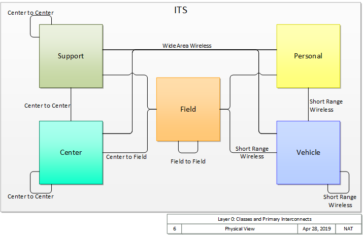
(Note that in this diagram we focus only on the primary interactions between systems; if we consider all possible interactions in the architecture, the connections between systems include more possibilities, as illustrated in this enhanced figure.)
Each of these Classes include one or more subsystems that are revealed at the next level of detail in the following figure. As shown, if we know the Class of a subsystem (e.g., Center), then we know generally how it interacts with other subsystems (e.g., a Center interacts with other Centers using 'Center to Center' Communications). The 'ITS Object' is the only subsystem defined for the "ITS" Class. Specific connections are not shown for the ITS Object in the figure since it can represent any ITS system, of any class, so it might be interconnected using any of the connections shown.
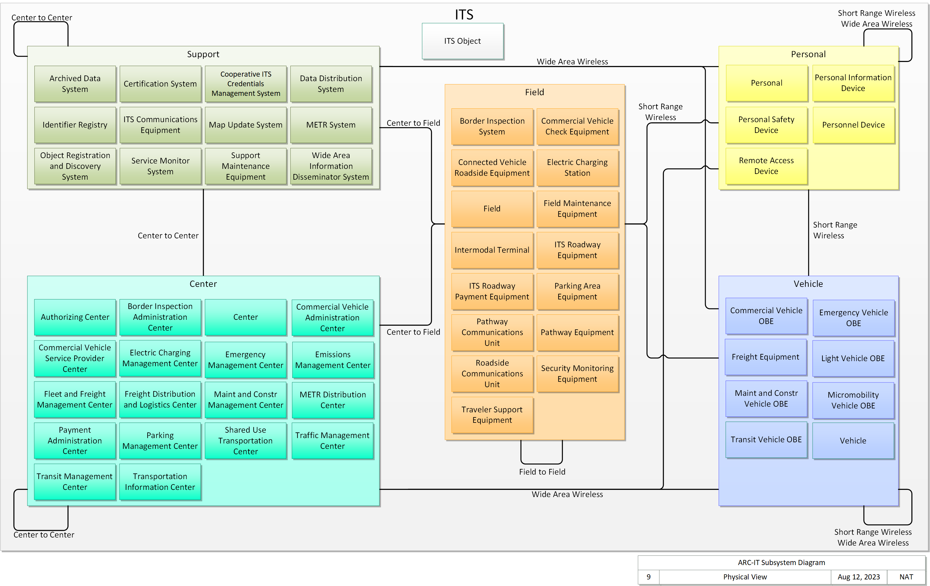
While it may not be intuitive at first, the "ITS Object" serves an important purpose in the ARC-IT physical view. The ITS Object is used in ARC-IT to define functionality and interfaces that may apply to any ITS device or system, regardless of Class. For example, obtaining security certificates and then using those certificates to support encryption and authentication is required for secure communications whether a particular ITS device is in a Center, a Support system, Field Equipment, Vehicle Equipment, or a Personal Device. Using the ITS Object, ARC-IT defines the functionality and interfaces for core functions like this just once, instead of having to redundantly define the same core functions for every subsystem.
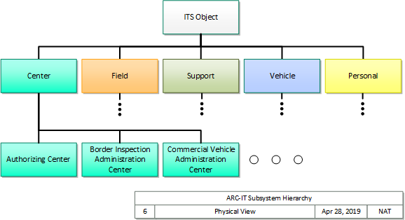
Considering this reuse objective, we can think of the ARC-IT physical objects in a hierarchy with the ITS Object at the top as shown in the following figure. The most generally-applicable functions and interfaces that may apply to all of ITS are defined at this level. Class-level physical objects like "Center" are shown at the next level of the hierarchy. Functions and interfaces that are shared by all ITS Centers, but not by subsystems of other classes, are defined in the "Center" physical object. Finally, the most specific physical objects like "Authorizing Center" and "Commercial Vehicle Administration Center" include more specific functions and interfaces unique to that type of Center.
For details on how the physical view is structured, see the physical viewpoint specification.